
My First Custom PCB: 6-Dot Tactile Braille Controller
A custom-fabricated PCB driving a 6-dot tactile matrix with MOSFET thermal actuators and I2C LCD interface.
// DOCUMENTED HARDWARE MEDIA
4 Photos from Verified LinkedIn Post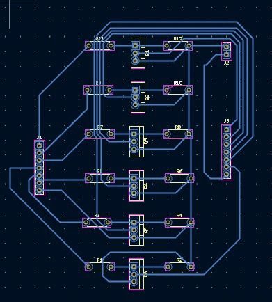
Fabricated PCB Board
Top and bottom copper routing with clean solder mask, ground plane, and silk screen labels.
// POST REFLECTION
Direct from LinkedIn"Six months ago, I took a major step in my hardware journey by designing and manufacturing my very first Printed Circuit Board."
As an ECE student, I’ve always leaned toward being a "practical implementer" — someone who loves taking theoretical circuit concepts and turning them into physical reality. Moving away from messy, high-impedance breadboard wiring to a clean, fabricated board was a massive shift in how I approach hardware design.
This specific PCB serves as the hardware foundation for a tactile Braille display. It controls a 6-dot matrix using thermal actuators driven by high-efficiency power MOSFETs, seamlessly translating digital incoming text into physical Braille characters through an Arduino microcontroller and an I2C LCD interface.
Modern Workflows & Firmware Co-Development
One of the biggest takeaways from this project was the power of modern iterative engineering. Without a traditional formal software background, I built the firmware and logic entirely by collaborating with modern AI tools. It proved to me that bringing complex electronic systems to life requires a deep intuitive grasp of hardware, schematic sanity, and the persistent drive to build.
Interactive Braille Hardware Simulator
Type any letter (A-Z) or click the buttons below to test how the controller energizes the 6 MOSFET gates and translates digital text to tactile dots:
Hardware Specifications
Official LinkedIn Post
Build It Yourself
The entire project is open-source. Grab the schematic diagrams, manufacturing Gerber files, and Arduino firmware on GitHub.